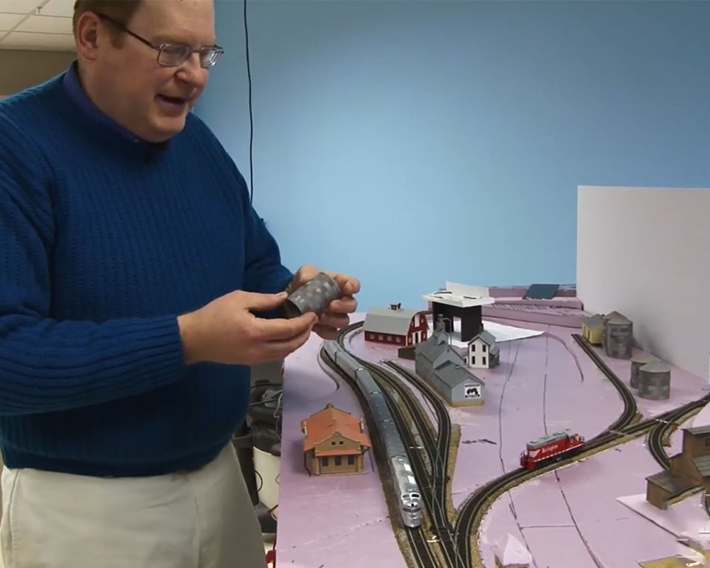
Track and wiring for the HO scale Eagle Mountain RR
| Last updated on November 23, 2020
Learn about transferring a track plan to benchwork tabletop, types of roadbed, tracklaying, and wiring the model railroad
| Last updated on November 23, 2020
Learn about transferring a track plan to benchwork tabletop, types of roadbed, tracklaying, and wiring the model railroad
Members enjoy 15% off any purchase in our store. Join Today!
Milwaukee, Racine & Troy HO scale steel cupola caboose - road name 1407
Don’t miss this exclusive HO scale Milwaukee, Racine & Troy steel cupola caboose.
i didn’t see this addressed in this video. any ideas on how to trim, connect, and lay flex track around curves? I generally remove ties as needed and solder 2 or 3 3 foot sections of track together and lay as one. Me being me, it’s a lot of trial & error-emphasis on error. Suggestions? thanks in advance.
Very informative and especially in the visual department. The camera operators are doing a great job of getting in the right places so we can see the details clearly, of what Eric is speaking on at the moment. Really helpful. Thanks. -Chris Eaton, Spokane, Wa.
Another useful and fine job! Thank you
Used a similar way to layout my track radius but since I had some obstructions in places, I first layed out the curves on sheet of 1 inch blue foam. Cut the foam out with the radius down the center and making it the width needed for clearances. That way I could fit it in between the obstructions and save for checking radius later too.
Where did you buy the suitcase connectors? My local building supply stores do not carry them. Thanks.
Excellent segment Eric and good teaching points. I too am at a similar point on my layout relaying some switches and using flex track around a 21 degree radii curve. Could you cover the laying of flex track on tight curves and avoiding kinks at the rail joiners? Thanks!
Does Neil know you guys have so much fun doing these videos? I still suspect fumes escaping from the paint booth!
Allan
Hi everyone, and thanks for your comments.
There are two sizes on Peco turnouts, no. 5s and no. 6s.
The no. 6s are the back-to-back turnouts at the edge of the layout on the shop side.
The curved turnouts are Walthers no. 6 1/2.
The flex track is Peco.
I made a template for each turnout I would use, so there are duplicates. That helped with planning.
I used an 18" radius turnout to draw the curves, then cheated outside of the curve a bit as I was getting everything aligned. The templates aren't perfectly precise, so once everything was together, I had to make adjustments to the curves for everything to fit. I knew I didn't want to go tighter than 18", so that's what I made my template.
The backdrop is high enough to keep me from seeing over the other side. It's attached to the tabletop with 2 x 3s. I screwed a 2 x 3 to the backdrop, then ran screws up from below to hold everything together.
I used a sharp no. 11 blade in a hobby knife and took my time to cut the templates.
I pinned the track on the outside because I didn't open the holes for track nails. Since I was using caulk, I didn't want unneeded holes in the ties.
And yes, while I was building the layout, Andy Sperandeo stopped by. He mentioned I had installed the roadbed inside out (or was it outside in – one or the other). You live, you learn.
Agree an actual track plan would be VERY nice. The first article said "the main curves on the railroad are 19" radius" but the video shows an 18" and a 20" radius template. ??? Eric shows several Peco templates, but never says which. The "layout at a glance" mentions only No.5 turnouts. Are these the only ones used?If so, why more than two templates in the video? If not, which turnouts are used where? This stuff may be second nature to an advanced modeler, but some of us need more help.
I applaud the expanded format of this year's project layout, but I had expected – perhaps foolishly – that this would allow MORE detail to be presented, not less.
I believe I heard him say 14 awg.
The way I make my cardboard templates, is after making the curve with a pencil, I then replace the pencil with an Xacto knife, and use the yard stick to make the arch.
Great article. In step 5 (Wiring) in your article, you tie the DCC bus to a hook, as an end of bus. Why don`t you simply run the DCC wires back to the booster to create a DCC loop. This will reduce the overall DCC wire resistance and assure higher voltage on long runs.
Interesting that you pinned the rail on the outside rather than using the nail holes In the center of the ties. You mentioned using 22 AWG for the feeders but did not mention the gauge of the bus.
It would be nice to know a track list.
The brand and number of the switches on the mine size is not mentioned.
I'm enjoying watching this project take shape — although it's a lot different from the layout I've been working on I've picked up some tips that I think will be helpful. Two questions…
1) How high is the backdrop? I know you mentioned it in passing on an earlier video, but it would be nice to know more. Related to that — do you have photos of it being attached before the foam was put in? I'd like to see more about that.
2) The cardboard curve templates are great, but how did you get the edges so smoothly rounded? I tried making my own out of foamcore, also using a trammel to draw the curves, but when it came to cutting them out I wasn't satisfied with the curved edge. I do still use them, but not with confidence.
And (belatedly), from another Pennsylvania to Wisconsin transplant, welcome to the Badger State from the Keystone State!
What brand flex track is that?
A very nice video on an interesting project layout. As the manufacturer of the Homasote roadbed (Cascade Rail Supply) I want to point out one mistake in using my products on the video. In the track laying segment as Eric is pinning the track down you can see where the kerfs (slots) in the roadbed both point to the outside of the roadbed. This is incorrect. There are two different types of roadbed in a package, one has the slots on the beveled edge and one on the inner edge. When curving the roadbed both sets of kerfs should be facing the inside of the curve. This closes up the kerfs and will keep the roadbed from breaking. Just a small correction on a really interesting layout.
I would have never thought of the cardboard templates! Great idea.
Fantastic video! You are working right at the place I am stuck. Transferring my track plan combined with two from your archives. I am also interested in the grade change as you go into the backdrop and how you did it? Any future segments on that would be epic!
Thanks, Dan
Great segment Eric. I used similar cardboard templates on my HO scale layout for curve radii and drawing centerlines as well as cutting plywood sections for elevated trackwork, I highly recommend that method. It is good to see that you"re getting lots of "help" from the rest of the staff on this project 🙂 Thanks.