Although used on many railroads, the Type G was so common on the New York Central that it was sometimes referred to as an NYC-style signal. It’s still used today.
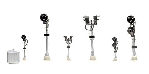
The single-head signal has one head with red, yellow, and green aspects. It’s used at the end of a block to indicate to following traffic that the block is occupied (red), a train has just exited a block and entered the next block (yellow), or the block is clear (green).
Bi-directional-head signals have two heads that face in opposite directions mounted on the same signal. These signals are used to guard the blocks from traffic moving from either direction.
Double-target signals are located at a turnout, such as at a passing siding. The top target controls the main line, and the bottom target governs the diverging route.
Each Atlas signal has a metal mast and plastic head, platform, ladder, and base. The signals feature great detailing, especially the in-scale, thin-profile ladders and platform. The base includes four mounting holes. A plastic bungalow is also included.
For bi-directional and double-head signals, you’ll need two SCBs and two BDBs for each signal. Atlas also recommends connecting a Custom Turnout Signal Controller, available from Custom Signals (www.customsignals.com), when installing a double-head signal.
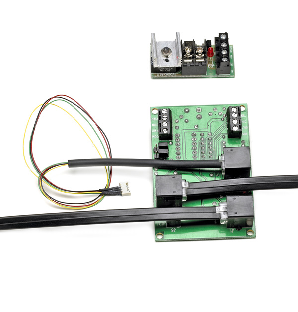
The Block Detector Board works by sensing current draw on an isolated section of track. That’s fine for a powered engine or lighted passenger car. A dummy engine or non-lighted car will need at least one resistor-equipped wheelset.
Basic installation of one signal is straightforward, following the provided wiring diagram. For one signal I used lengths of solid 22AWG red and black wire to connect to the screw terminals on the circuit boards. The SCB has two sets of PWR and COM terminals. One set connects the first signal and SCB to the power supply, and the other set connects to the BDB’s PWR and COM terminals. I connected the DIN input on the SCB to the DET input on the BDB.
Then I connected the BDB’s PWR IN terminal to the track power bus and the TO TRK ter-minal to the gapped rail by soldering a green 22AWG solid wire to the metal rail joiner at the center of the block. You could use terminal rail joiners instead.
Each circuit board has a light-emitting diode (LED) that lights if the board is wired correctly. After connecting the boards and power supplies, I attached the signal to the supplied jumper wire’s micro connector. I then plugged the jumper’s RJ-11 plug into a telephone-style jack (J3) on the SCB.
For more-realistic operation, the signals can be used in integrated operation. In this mode the yellow aspect is controlled by occupancy of the blocks behind or in front of the train, instead of a timer.
For this mode, the PWR and COM connections go to the PWR and COM connections of the next block signal’s SCB and so on. The BDB’s PWR and COM terminals are then connected directly to the auxiliary power supply.
For integrated signal operation, you can use Atlas signal cables, which have telephone-style connectors that link SCBs together. These cables are available in 7-, 15-, and 24-foot lengths and range in price from $3.95 to $10.95. I connected our test signals as per the instructions and found that they functioned correctly, with the yellow aspect of the first block turning green as soon as the train exited the second block.
The cables simplify installation. However, the SCB includes screw terminals for connecting SCBs without using the signal cables.
The SCB also has a DOUT connection for an LED or relay. It follows the input of the DIN connection to the BDB and activates the LED or relay when a block is occupied.
With the signals already wired for integrated operation, all I had to do was remove the jumper across the JP2 terminal on the SCB.
Wiring is more complicated for stand-alone approach-lit operation since the signal’s SCB would need to be connected to not only the BDB associated with its block but also to the BDBs for the blocks before and after it, using the SCB’s J6 and YIN terminals.
Although the Atlas signals require installing a few components, the extra effort will reward those who want a reliable, realistic signal system for their layout