For well over a century, copper mines and their structures dotted the landscape in Michigan’s Upper Peninsula. I was born there and several generations of my family worked in the mines. The last one closed in the late 1960s, marking the end of an era for thousands of people.
Most of the facilities were removed and nature reclaimed the sites, although a few have been preserved. A popular preserved mining location is the Quincy Mine in Hancock.
The mine buildings for my Copper Country Central Railroad are based on those of Quincy. The shaft rockhouse and hoist house still exist as part of the Quincy Mine Hoist Association where I took photos and obtained plans for these structures. The boilerhouse and stamp mill have been reduced to ruins, so I used my photos taken of the ruins, combined with those from the Library of Congress Historic American Engineering Record Collection.
I will describe how I scratch built the shaft rockhouse, hoist house, and boiler house as few commercial structures exist for these buildings.
The structures above ground are known as the surface plant – what we usually model on our layouts. I decided to also model the underground mine, which I will discuss a bit later. Knowing that it would take some time to build the layout, I covered the plywood and foam insulation board surface with a Woodland Scenics grass mat. This made the layout presentable while I built the structures. I eventually removed the mat as buildings were added and the permanent scenery completed.
Shaft rockhouse
The shaft rockhouse draws the most attention. It was at the entrance to the mine where the copper-bearing rock was raised to the surface, then sorted and crushed. The rock was then loaded into ore cars.
You may have noticed that I use the name “shaft rockhouse.” In the early years of copper mining, the rockhouse was separate from the shaft house. By the late 1800s, these structures were often combined into one building.
I based my model on Quincy’s shaft rockhouse No. 2. Researching this structure, I discovered that selective compression would be applied in order to fit everything on the layout. Even reduced in size, the structure stands 27” tall. It dominates the layout just as the prototype.
The first order of business is to measure the clearance needed for the ore cars under the loading chute. Mine measures 5 by 5 inches to allow some extra space in case a boxcar is accidentally pushed into the siding.
The concrete base is made of three pieces of dimensional lumber painted a concrete color. The cylindrical rock bin is a coffee can that I airbrushed Polly Scale Mineral Red — This line is discontinued. See the resources list at the end of this article for available paint options. . The can is topped with a square piece of wood, creating a floor for the rest of the structure above it.
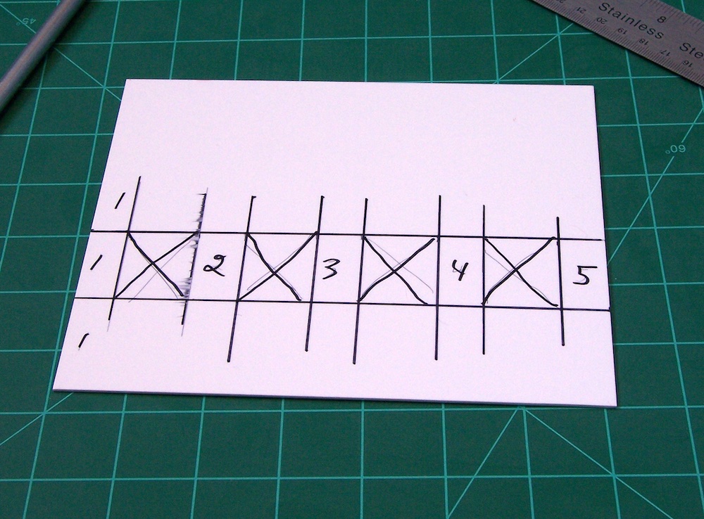
Since this is a tall structure, I chose to use .080” styrene to reduce the need for a lot of bracing. The window openings could be cut out individually, but the easiest way is a technique used by modelers for decades. Essentially, it involves cutting the wall apart and cementing it back together, minus the pieces from the window openings. It is a fast method, especially if you use fast-setting cement. Extra bracing, using styrene ¼”square stock, is also a good idea on a structure this large.
One of the characteristics that make this shafthouse so interesting is the many shapes and angles, though making the construction more difficult. The top section is narrower than the mid-section. The best way I found to build this is to simply make this upper section reach down to the floor above the rock bin. The mid-roof can then be added in-between. This will make for a stronger building because the hoist cables will be passing through the upper section.
The roof should be removable to allow you to string the hoist cables. The upper section also has a rectangular area behind it, which is left open on top. This was a vent on the prototype.
The sloped rear section of the shaft is then added with a cardboard template to get the exact shape needed to fit the side pieces. It’s best to make the roof removable as well to add interior details and lights. I covered the styrene surfaces with Plastruct corrugated siding from 1 ¾” cut strips — overlapping the lower strip by ¼ inches. Clear silicone sealant was then used to attach the siding. I airbrushed Grandt Line No. 3707 clear windows using Polly Scale Soo Line Red, then attached two pieces of .010” clear styrene for each window. This is the only part of the project that is truly monotonous as the structure has 30 windows!
Next is the batter brace for the headframe sheaves at the front of the shafthouse, with only the lower portion being visible. I used styrene, ¼” H-columns and ⅛”, angle structure shapes to make the brace, then painted them red. Additional H-columns to the cylindrical rock bin were also made and painted.
I added a little weathering at this point, keeping in mind that most working mines were well-maintained. Various shades of brown and black chalks were used on both the concrete base and tracks. The corrugated siding received a light airbushing of earth and rust colors.
Since the headframe sheaves were enclosed due to harsh winters in the Keweenaw Peninsula you don’t need to model them. However, I still wanted the basic shape as well as a place to thread the hoist cables. A round cardboard tube was cut to size with round, cardstock ends added. Two vertical slots in the shafthouse’s front wall were then cut directly in front of the tube, followed by the hoist cables added through the slots.
The angle of the rear portion of the entire structure follows the slope of the shaft. The shaft itself is essentially a hole in the ground where the rock is hauled up from the mine in skips traveling on rails. Most of this isn’t seen on the layout, but I still added basic details. Four holes were drilled through the tabletop where the shaft would be.I used a piece of foamcore board, installed at an angle, and added some HO-scale rails to form the skip. The skips, themselves, were built from .020” styrene, and painted black with some weathering.
Hoist house
The hoist raised and lowered the skips in and out of the mine. Cables wound around a steam-powered hoist drum. I chose to model the hoist because my grandfather was a hoist operator and wanted to honor him on my layout.
The model was constructed from .060” styrene with door and window openings cut in the same manner as the shafthouse. I assembled the four wall sections, then covered them with Plastruct 91560 Random Coursed Stone sheet using spray adhesive.
By attaching the stone sheets after assembly, I was able to line up the individual stones at the comers. The walls were airbrushed with Polyscale Rust, while the interior was painted black. I installed Grandt Line No. 3712 windows, window sills from Plastruct No. 91606 Rough Brick and a No. 3602 door, painting them all mineral red with added .010” clear styrene. I also decided to add a freight door at the rear of the building.
The removable roof is made from the same .060” styrene, held together by triangular
gussets cut to the same shape as the roof gables on the end walls. The roof is made from Plastruct corrugated siding.
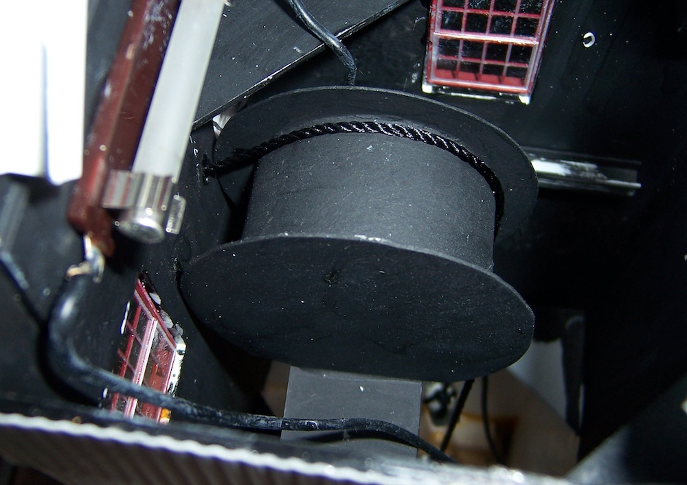
The front of the real-life hoist house has two horizontal slots for the cables. As the hoist drum turns, one cable is wound in while the other is wound out. The prototype photo shows the grooves in the hoist drum where the cables ride. I was working on a home remodeling project and noticed the threads on a PVC pipe fitting that resembled similar grooves. By gluing two fittings together, I was able to create a convincing hoist drum.
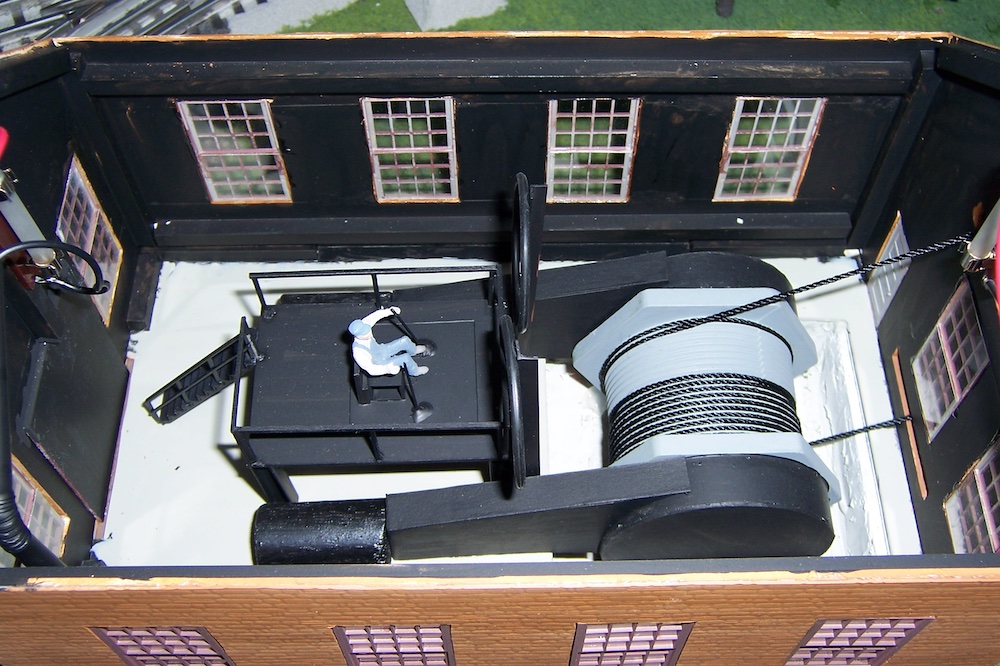
Hoist drums were often located partially below the floor. Cutting out a section of foam under the hoist house allowed me to duplicate this feature. I even made a basic representation of the steam engine. The building windows are large, much of the detailing is difficult to see, even with the interior lights on.
The hoist operator’s platform is a styrene platform supported by H-columns. He communicated with the men in the mine using bells, and knew the location of the skips by two large dials called “miniatures.” These are represented on my model using a couple of O-rings. An Arttista engineer figure represents hoist operator Tom (my grandfather’s name).
Pulley stands, located between the hoist house and shaft house, supported the cables. I used ¼” square hardwood, assembled using white glue and HO track nails to reinforce the joints. The cable stands were then glued onto the layout but won’t be finished until the hoist cables are in place.
The hoist cables for the model are from a heavy black thread I purchased at a craft store. It measures 1/16 inches in diameter, and looks somewhat like the 1 ⅝” wire rope used on the prototype. The wire rope fitting attaches to the skip as an electrical connector, which I simply crimped onto the thread.
One cable extends from the bottom of the hoist drum and exits through the lower slot in the front wall of the hoist house. The other cable extends from the top of the drum through the upper slot. I threaded the cables through the upper section of the pulley stands and into the proper vertical slots in the shafthouse, All while avoiding rigidly attaching them as they might be damaged if bumped. I also decided to tie a ⅜” nut onto the end of the cable and let the weight of the nut hold it over the cardboard tube in the top of the shafthouse.
The sheaves to our pulley stands can then be added. The pulleys are Grandt Line No. 3525 sheaves inserted into some stiff wire. Glueing the sheaves to the wire should be avoided as they need to be movable to position them correctly. Instead, by holding the sheave up to the cable, I carefully marked where the holes for the wire and drill them with a small diameter bit in a pin vise for the wires to be inserted.
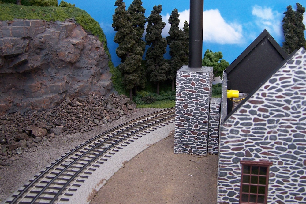
The final scenery around the structures can be added, usually with a great deal of poor rock covering the ground. Poor rock is brought up from the mine that doesn’t contain copper, so it can be used for building materials and ballast. The rock I used was actual poor rock from the mining sites, but any dark-colored rock will work. I then added Woodland Scenics ground foam and several trees, along with figures from Arttista, MTH, and Woodland Scenics.
Boiler house
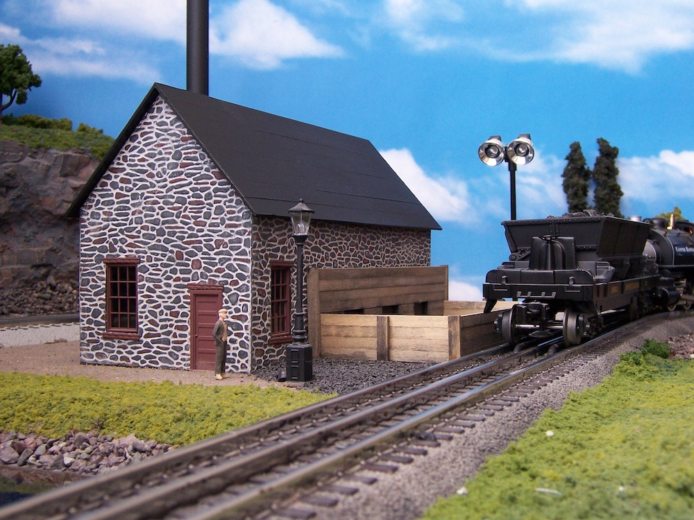
The boiler house produced the steam used to power the hoists. Compared to the other structures on my layout, this is an easier build. The walls and roof were made in the same way as the hoist house, but with different materials to cover the styrene.
The prototype boiler house my model is based on was constructed of poor rock. Plastruct No. 91565 Field Stone sheet was a good match, with a paint of dark gray and random stones receiving a mineral red color. I then rubbed some spackling compound into the mortar joints and lightly wiped the wall with a damp cloth to remove the excess from the surface of the stones. A wash of black acrylic paint darkened the mortar.
The windows are Grandt Line No. 3718 painted mineral red. Window sills are made from the same Plastruct 91606 brick used on the hoist house.
The chimney has two parts: a lower stone portion, made exactly like the main building; and an upper metal section, which is the length of a brass tubing painted black.
I covered the boiler house roof with Scotch High Adhesion No. 2020 masking tape, painted black. Like the hoist house, the roof is removable. Cardboard tubes painted black were used to represent some boilers inside the building. The windows are not large enough to really see much of the interior, especially considering how the boiler house is situated on the layout. Nevertheless, I wanted the appearance of having something inside.
The coal bin, which is also the receiving bin for the operating coal dump cars, was next. I used basswood for the bin, and gave each piece stained brown before washing them with a black shoe dye and rubbing alcohol.The base and back of the bin are made from 3/32” basswood withthe front and sides being ⅛” x ¼” stripwood glued on each end with the posts glued to the sides. Make sure the side dump cars will clear the sides of the bin when working on this project.
The coal doors going into the boiler house are actually on the bin rather than on the building. This was necessary because the bin couldn’t have any openings where the coal could spill out when it was being emptied. The coal doors are made by painting black squares on the back sheet of the bin, and laminated with stripwood around these squares.
I then added a couple of small Atlas trackside shanty and GC Laser oil house kits at the rockhouse. When they are a red color, the shanties make for nice-looking supply sheds. Of course, these could also be scratchbuilt, but I just needed small generic buildings. Sometimes, it’s fun to assemble a kit for a change.
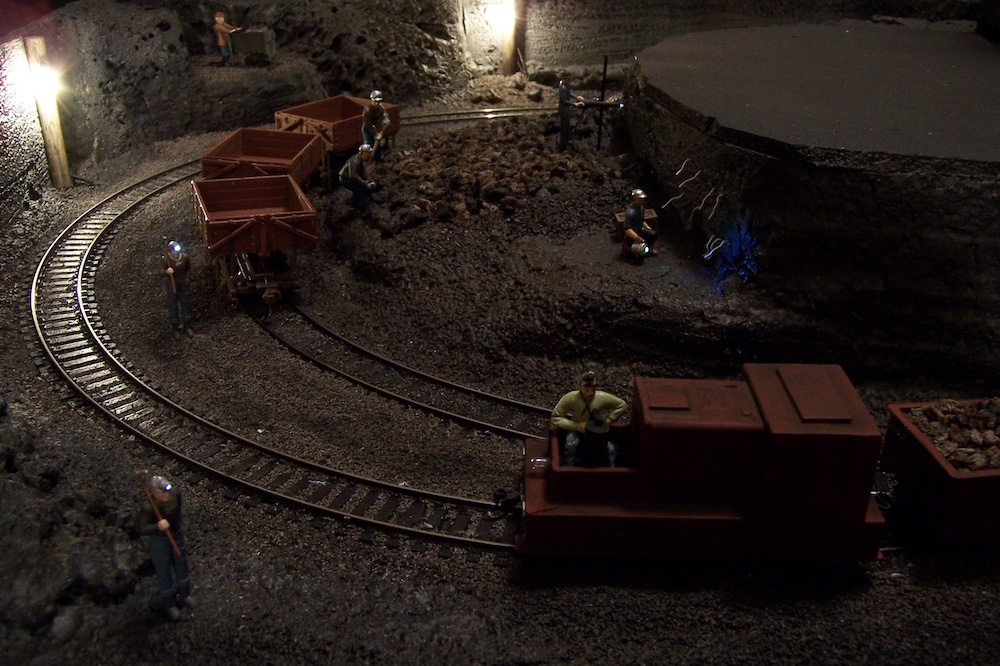
Underground mine
Some might wonder why I would want to model an underground mine. The first goes back to when I was a kid. My family and I visited a mining museum in Caspian, Michigan, and it had a small operating cutaway display of a mine. This memory stayed with me all these years, so I decided I would try something similar for my layout. My other reason is simply because I don’t know of anyone else who has done it before.
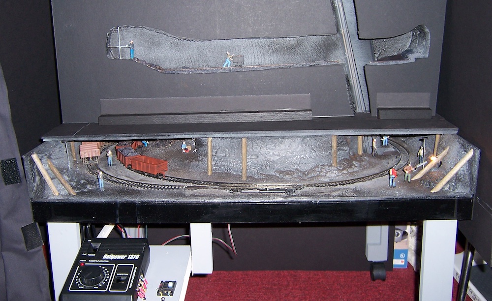
This underground mine is essentially a small layout underneath the main layout. It could be classified as On30 since I used HO track in the mine. The layout is only 24 x 32 inches. It certainly could be larger, but I was trying to achieve an overall effect. The locomotive and some of the tram cars are kitbashed products in HO, although I also used some Bachmann No. 29801 On30 mining cars.
Benchwork is built using common techniques, but because of the small size, I used lighter components. It was a simple 1” x 2” frame with a piece of ¼” plywood attached using glue and 18-gauged brads. A piece of thin foam cut from a piece of fan-fold insulation was glued to the plywood for noise reduction. I decided to make a drawer-type control panel using a couple of drawer slides. Casters on the 2” x 2” legs allowed me to roll the mine out from under the layout for construction. A prototype mine has many levels, so I cut a square opening in the plywood to give the illusion of the shaft continuing downward.
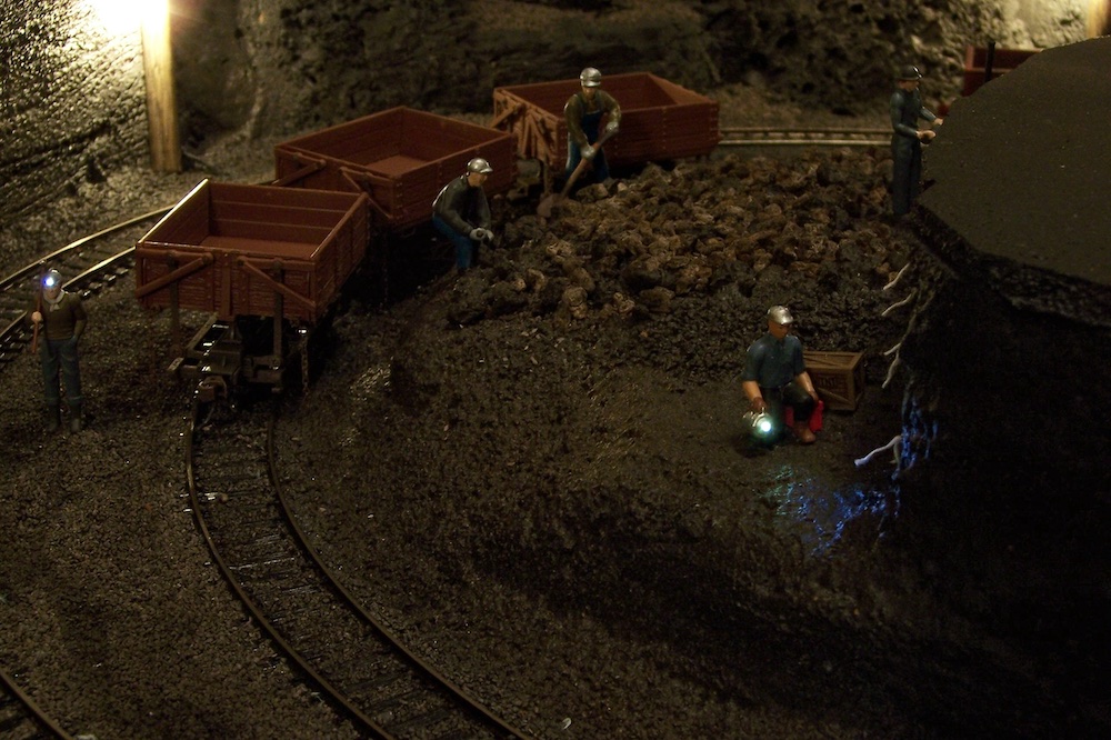
The track makes a simple loop with one siding where the tram cars are loaded. I used Atlas HO code 100snap switch and flextrack — the flextrack curves are at 20 inches in diameter with the siding even sharper at 15”. Ballasting the track is next. Even after studying photos of the mines, I am not sure if the track was purposely ballasted or if it was just buried in debris. Either way, I added some dark gray HO scale ballast.
For the scenery, I wanted to try some new techniques, deciding on a method used by the CTT staff when they built their Cascade & Timber Trail project layout in 2009. This involved using an expanding foam insulation product to create rockwork and fill in gaps between the foam sheets. I shaped the foam using an old knife and a wire brush.
Now it is time to paint the track and foam. I first applied a coat of black Rust-Oleum Aqua water-based spray paint, followed by light mists of oxide red and gray. I cleaned the tops of the rails with a Walthers Bright Boy.
I then returned to the shaft where the cut out was made in the plywood. I extended the skip road about 5″ below the surface with some foamcore and added some HO rails for the skips. The extra skip made earlier was then added to the skiproad.
Obviously, this skip should be on the opposite side of the skiproad from the skip in the shaft-rockhouse. This skip will also be on the side corresponding to the side of the hoist drum with less cable. Like the skip in the shafthouse, a piece of heavy thread with an electrical fitting crimped on the end was attached. A chute was also added between the edge of the opening and the skip. I made this chute simply by cutting and bending a piece of cardstock. RThe were embossed using a pen and pressed into the back of the cardstock, which was placed over an old magazine. I painted the chute with [discontinued] Pactra Gunmetal and weathered it with chalks.
Mine equipment
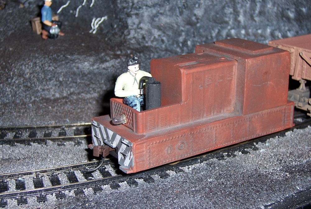
We needed a mine locomotive, so I once again looked to the world of HO and chose a Model Power Porter diesel switcher. Much of the shell was modified, but I didn’t want to change the location of the motor or the weight. Determining the areas to remove, I cut off the top of the cab using a razor saw and then made an enclosure for the motor using .020” styrene. A coat of oxide red primer completed the body shell. I then reassembled the locomotive and made a seat and a control stand using small pieces of basswood. The motorman came from a set of MTH from the miner control figures. The headlight bulb was installed in a hole I drilled at the front.
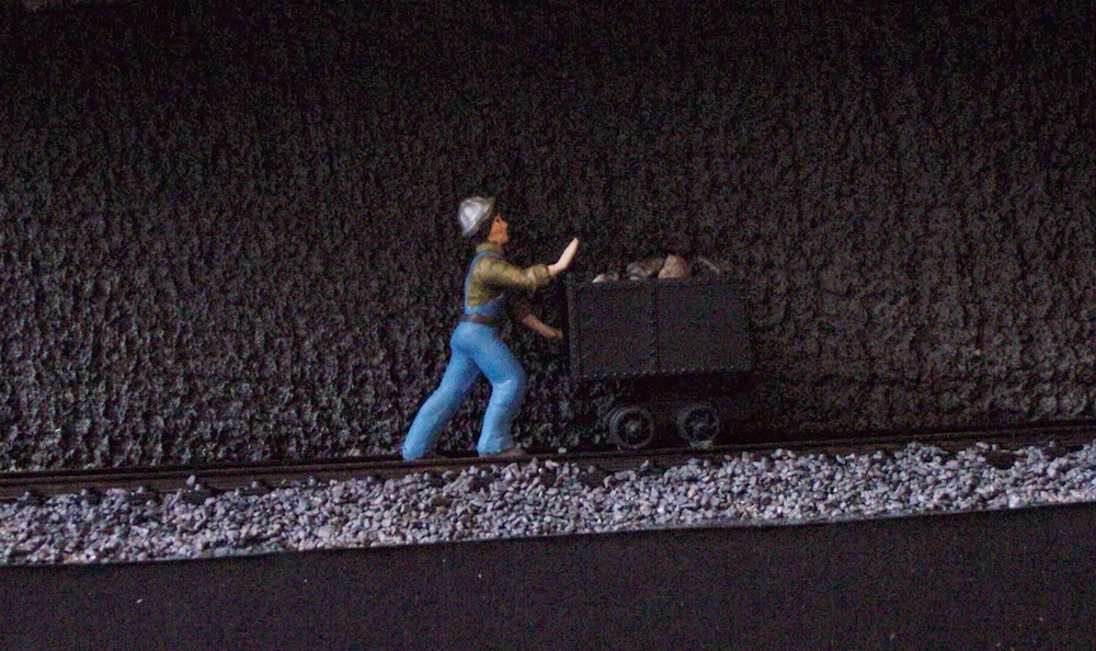
Bachmann makes some excellent On30 mine cars that are perfect for tram cars. Along with this equipment, I wanted to add a little variety. So I kitbashed more cars from some inexpensive Tyco gondolas. I reused the trucks even though they are not prototypical for a tram car. The low-light levels of the mine combined with their black color makes them less noticeable.
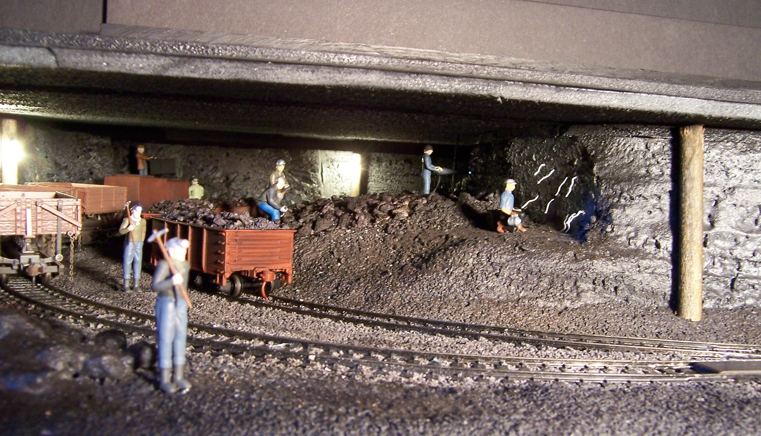
I also made good use of the illuminated figures from Model Power. These included the miner with the lighted helmet, the man with a flashlight, and the man with a jackhammer. I modified the jackhammer to look like a one-man rock drill. Many of the figures were modified and repainted to give a typical appearance of miners. Several rock drills were made using pieces of l8 gauge stranded wire. I stripped some insulation from both ends and twisted one end together to form the drill steel (aka the drill bit). The strands on the other end were formed to generally look like the operator end of the drill. The wire strands on both ends were then filled with solder to hold them together. A length of stiff wire is used for the support. Once painted gray, these make nice details for very little cost. These drills may not look exactly like the real ones, but I doubt most visitors have ever seen a century-old rock drill.


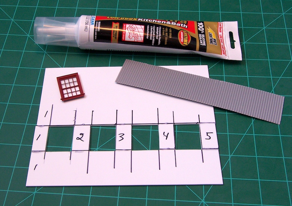
The author uses silicone sealant to attach the windows and siding. Karl Sablich photo


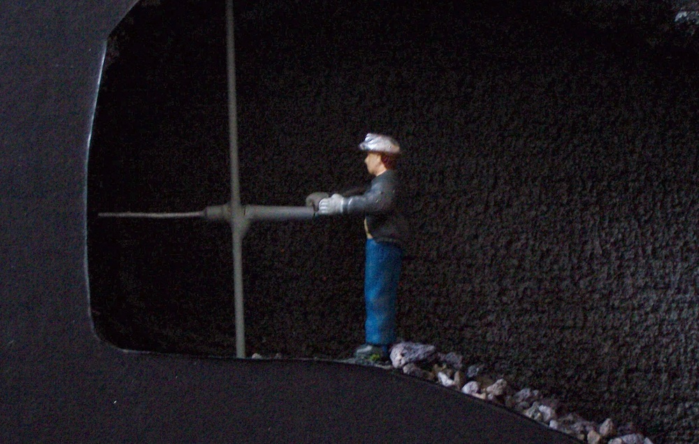
The author used pieces of painted 18 gauge wire to form the drills. Karl Sablich photo


Final touches
I made a removable ceiling for the mine using a sheet of foam carved in the same way as the rest of the rockwork. I then positioned the thick, back-painted foam sheets upright between the operating level and the bottom of the main layout. All of these sections above the mine are removable to facilitate maintenance.
Every mining company was different, just like every layout is different. The structures I built may not be suitable for everyone, but will hopefully mine out inspiration for your own mining complex from Michigan’s Upper Peninsula.
Note: My Copper Country Central layout was featured in the February 2014 issue of CTT. I described the construction of the stamp mill and its setting in the February 2012 issue.
Resources
Acrylic paints for airbrushing
Model railroad adhesives and glues
Share this article